Tool Mentor:
Creating a Software Architecture Document Using Rational SoDA
Purpose
This tool mentor describes how to use Rational SoDA to create a Software
Architecture Document. SoDA automates the generation of the report so that it is
created quickly and accurately. You can generate a Software Architecture
Document with either the Microsoft Word or Adobe FrameMaker version of SoDA. To
create this report, SoDA collects architecturally significant aspects from a
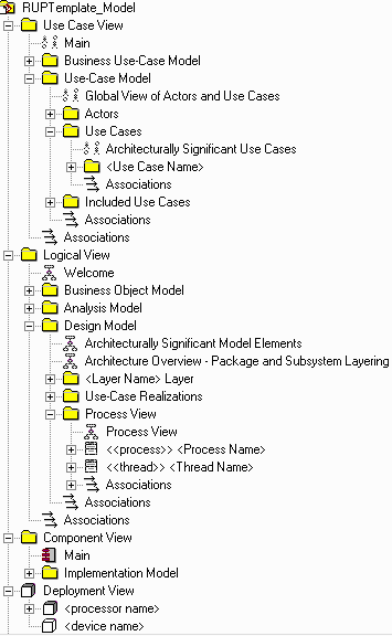
Rational Rose model. This works only if the model follows the structure
and naming convention for the Rose model.
Related Rational Unified Process information: Artifact:
Software Architecture Document.
Overview
This tool mentor is applicable when running Windows 98, Windows 2000, NT 4.0,
Windows XP, Solaris, or HP-UX.
To create a the Software Architecture Document using SoDA, use the procedure
for your version of the product:
- From anywhere in Rational Rose, click Report > SoDA Report.
- When the list of available reports appears in SoDA, select Rational
Unified Process Software Architecture Document.
- Click OK to generate the report.
- From the FrameMaker button-bar, click New. Double-click SoDA,
then double-click RoseDomain and choose the RUPSoftwareArchitectureDocument.fm
template.
- Edit the Connector and enter the name of the model.
- Click File > Save As to save the template to a personal or
project directory.
You may want to change the name of the template to reflect the name of the
use case; for example, ConductTransactionsReport.fm.
- Click SoDA > Generate Document.
- Review the generated document.
The next time you want to generate this same document, simply open the
document and click SoDA > Generate Document.
 |
The following lists the diagrams
that SoDA extracts from the Rose model for inclusion in the Software Architecture Document:
- The use cases and actors that are architecturally significant are
shown in the Use-Case View
section of the document.
- The classes, interfaces, packages, and subsystems that are
architecturally significant are shown in
the Logical View section of the document.
- The packages that represent layers in the design model are shown in the Logical View section of the
document.
- Any diagram in the Process View package is shown in the
Process View section of the document.
- Any diagram in the Implementation Model package is shown in
the Implementation View section of the document.
- Any diagram in the Deployment View is shown in the Deployment View
section of the document.
|
Copyright
© 1987 - 2001 Rational Software Corporation
| |

|
 Tool Mentors >
 Rational SoDA Tool Mentors >
 Creating a Software Architecture Document Using Rational SoDA
 Tool Mentors >
 Rational SoDA Tool Mentors >
 Creating a Software Architecture Document Using Rational SoDA
