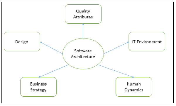
The architecture of a system describes its major components, their relationships (structures), and how they interact with each other. Software architecture and design includes several contributory factors such as Business strategy, quality attributes, human dynamics, design, and IT environment.
We can segregate Software Architecture and Design into two distinct phases: Software Architecture and Software Design. In Architecture, nonfunctional decisions are cast and separated by the functional requirements. In Design, functional requirements are accomplished.
Architecture serves as a blueprint for a system. It provides an abstraction to manage the system complexity and establish a communication and coordination mechanism among components. It defines a structured solution to meet all the technical and operational requirements, while optimizing the common quality attributes like performance and security.
Further, it involves a set of significant decisions about the organization related to software development and each of these decisions can have a considerable impact on quality, maintainability, performance, and the overall success of the final product. These decisions comprise of −
Selection of structural elements and their interfaces by which the system is composed.
Behavior as specified in collaborations among those elements.
Composition of these structural and behavioral elements into large subsystem.
Architectural decisions align with business objectives.
Architectural styles guide the organization.
Software design provides a design plan that describes the elements of a system, how they fit, and work together to fulfill the requirement of the system. The objectives of having a design plan are as follows −
To negotiate system requirements, and to set expectations with customers, marketing, and management personnel.
Act as a blueprint during the development process.
Guide the implementation tasks, including detailed design, coding, integration, and testing.
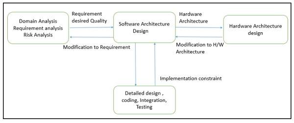
Domain analysis, requirements analysis, and risk analysis comes before architecture design phase, whereas the detailed design, coding, integration, and testing phases come after it.
The primary goal of the architecture is to identify requirements that affect the structure of the application. A well-laid architecture reduces the business risks associated with building a technical solution and builds a bridge between business and technical requirements.
Some of the other goals are as follows −
Expose the structure of the system, but hide its implementation details.
Realize all the use-cases and scenarios.
Try to address the requirements of various stakeholders.
Handle both functional and quality requirements.
Reduce the goal of ownership and improve the organization’s market position.
Improve quality and functionality offered by the system.
Improve external confidence in either the organization or system.
Software architecture is still an emerging discipline within software engineering. It has the following limitations −
Lack of tools and standardized ways to represent architecture.
Lack of analysis methods to predict whether architecture will result in an implementation that meets the requirements.
Lack of awareness of the importance of architectural design to software development.
Lack of understanding of the role of software architect and poor communication among stakeholders.
Lack of understanding of the design process, design experience and evaluation of design.
A Software Architect provides a solution that the technical team can create and design for the entire application. A software architect should have expertise in the following areas −
Expert in software design, including diverse methods and approaches such as object-oriented design, event-driven design, etc.
Lead the development team and coordinate the development efforts for the integrity of the design.
Should be able to review design proposals and tradeoff among themselves.
Expert on the system being developed and plan for software evolution.
Assist in the requirement investigation process, assuring completeness and consistency.
Coordinate the definition of domain model for the system being developed.
Expert on available technologies that helps in the implementation of the system.
Coordinate the selection of programming language, framework, platforms, databases, etc.
Expert on software development methodologies that may be adopted during SDLC (Software Development Life Cycle).
Choose the appropriate approaches for development that helps the entire team.
An architect is expected to deliver clear, complete, consistent, and achievable set of functional goals to the organization. Besides, he is also responsible to provide −
A simplified concept of the system
A design in the form of the system, with at least two layers of decomposition.
A functional description of the system, with at least two layers of decomposition.
A notion of the timing, operator attributes, and the implementation and operation plans
A document or process which ensures functional decomposition is followed, and the form of interfaces is controlled
Besides, facilitating the technical work among team members, it has also some subtle roles such as reinforce the trust relationship among team members and protect team members from the external forces that could distract them and bring less value to the project.
Quality is a measure of excellence or the state of being free from deficiencies or defects. Quality attributes are the system properties that are separate from the functionality of the system.
Implementing quality attributes makes it easier to differentiate a good system from a bad one. Attributes are overall factors that affect runtime behavior, system design, and user experience.
They can be classified as −
Static Quality Attributes − Reflect the structure of a system and organization, directly related to architecture, design, and source code. They are invisible to end-user, but affect the development and maintenance cost, e.g.: modularity, testability, maintainability, etc.
Dynamic Quality Attributes − Reflect the behavior of the system during its execution. They are directly related to system’s architecture, design, source code, configuration, deployment parameters, environment, and platform. They are visible to the end-user and exist at runtime, e.g. throughput, robustness, scalability, etc.
Quality scenarios specify how to prevent a fault from becoming a failure. They can be divided into six parts based on their attribute specifications −
Source − An internal or external entity such as people, hardware, software, or physical infrastructure that generate the stimulus.
Stimulus − A condition that needs to be considered when it arrives on a system.
Environment − The stimulus occurs within certain conditions.
Artifact − A whole system or some part of it such as processors, communication channels, persistent storage, processes etc.
Response − An activity undertaken after the arrival of stimulus such as detect faults, recover from fault, disable event source etc.
Response measure − Should measure the occurred responses so that the requirements can be tested.
The following table lists the common quality attributes a software architecture must have −
| Category | Quality Attribute | Description |
|---|---|---|
| Design Qualities | Conceptual Integrity | Defines the consistency and coherence of the overall design. This includes the way components or modules are designed. |
| Maintainability | Ability of the system to undergo changes with a degree of ease. | |
| Reusability | Defines the capability for components and subsystems to be suitable for use in other applications. | |
| Run-time Qualities | Interoperability | Ability of a system or different systems to operate successfully by communicating and exchanging information with other external systems written and run by external parties. |
| Manageability | Defines how easy it is for system administrators to manage the application. | |
| Reliability | Ability of a system to remain operational over time. | |
| Scalability | Ability of a system to either handle the load increase without impacting the performance of the system or the ability to be readily enlarged. | |
| Security | Capability of a system to prevent malicious or accidental actions outside of the designed usages. | |
| Performance | Indication of the responsiveness of a system to execute any action within a given time interval. | |
| Availability | Defines the proportion of time that the system is functional and working. It can be measured as a percentage of the total system downtime over a predefined period. | |
| System Qualities | Supportability | Ability of the system to provide information helpful for identifying and resolving issues when it fails to work correctly. |
| Testability | Measure of how easy it is to create test criteria for the system and its components. | |
| User Qualities | Usability | Defines how well the application meets the requirements of the user and consumer by being intuitive. |
| Architecture Quality | Correctness | Accountability for satisfying all the requirements of the system. |
| Non-runtime Quality | Portability | Ability of the system to run under different computing environment. |
| Integrality | Ability to make separately developed components of the system work correctly together. | |
| Modifiability | Ease with which each software system can accommodate changes to its software. | |
| Business quality attributes | Cost and schedule | Cost of the system with respect to time to market, expected project lifetime & utilization of legacy. |
| Marketability | Use of system with respect to market competition. |
Software architecture is described as the organization of a system, where the system represents a set of components that accomplish the defined functions.
The architectural style, also called as architectural pattern, is a set of principles which shapes an application. It defines an abstract framework for a family of system in terms of the pattern of structural organization.
The architectural style is responsible to −
Provide a lexicon of components and connectors with rules on how they can be combined.
Improve partitioning and allow the reuse of design by giving solutions to frequently occurring problems.
Describe a particular way to configure a collection of components (a module with well-defined interfaces, reusable, and replaceable) and connectors (communication link between modules).
The software that is built for computer-based systems exhibit one of many architectural styles. Each style describes a system category that encompasses −
A set of component types which perform a required function by the system.
A set of connectors (subroutine call, remote procedure call, data stream, and socket) that enable communication, coordination, and cooperation among different components.
Semantic constraints which define how components can be integrated to form the system.
A topological layout of the components indicating their runtime interrelationships.
The following table lists architectural styles that can be organized by their key focus area −
| Category | Architectural Design | Description |
|---|---|---|
| Communication | Message bus | Prescribes use of a software system that can receive and send messages using one or more communication channels. |
| Service–Oriented Architecture (SOA) | Defines the applications that expose and consume functionality as a service using contracts and messages. | |
| Deployment | Client/server | Separate the system into two applications, where the client makes requests to the server. |
| 3-tier or N-tier | Separates the functionality into separate segments with each segment being a tier located on a physically separate computer. | |
| Domain | Domain Driven Design | Focused on modeling a business domain and defining business objects based on entities within the business domain. |
| Structure | Component Based | Breakdown the application design into reusable functional or logical components that expose well-defined communication interfaces. |
| Layered | Divide the concerns of the application into stacked groups (layers). | |
| Object oriented | Based on the division of responsibilities of an application or system into objects, each containing the data and the behavior relevant to the object. |
There are four types of architecture from the viewpoint of an enterprise and collectively, these architectures are referred to as enterprise architecture.
Business architecture − Defines the strategy of business, governance, organization, and key business processes within an enterprise and focuses on the analysis and design of business processes.
Application (software) architecture − Serves as the blueprint for individual application systems, their interactions, and their relationships to the business processes of the organization.
Information architecture − Defines the logical and physical data assets and data management resources.
Information technology (IT) architecture − Defines the hardware and software building blocks that make up the overall information system of the organization.
The architecture design process focuses on the decomposition of a system into different components and their interactions to satisfy functional and nonfunctional requirements. The key inputs to software architecture design are −
The requirements produced by the analysis tasks.
The hardware architecture (the software architect in turn provides requirements to the system architect, who configures the hardware architecture).
The result or output of the architecture design process is an architectural description. The basic architecture design process is composed of the following steps −
This is the most crucial step because it affects the quality of the design that follows. Without a clear understanding of the problem, it is not possible to create an effective solution. In fact, many software projects and products are considered as unsuccessful because they did not actually solve a valid business problem or have a recognizable return on investment (ROI).
In this phase, build a baseline for defining the boundaries and context of the system. Decomposition of the system into its main components is based on the functional requirements. The decomposition can be modeled by using a design structure matrix (DSM), which shows the dependencies between design elements without specifying the granularity of the elements.
In this step, the first validation of the architecture is done by describing a number of system instances and this step is referred as functionality based architectural design.
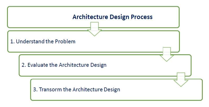
Each quality attribute is given an estimate, so in order to gather qualitative measures or quantitative data, the design is evaluated. It involves evaluating the architecture for conformance to architectural quality attributes requirements.
If all the estimated quality attributes are as per the required standard, the architectural design process is finished. If not, then the third phase of software architecture design is entered: architecture transformation. However, if the observed quality attribute does not meet its requirements, then a new design must be created.
This step is performed after an evaluation of the architectural design. The architectural design must be changed until it completely satisfies the quality attribute requirements. It is concerned with selecting design solutions to improve the quality attributes while preserving the domain functionality.
Further, a design is transformed by applying design operators, styles, or patterns. For transformation, take the existing design and apply design operator such as decomposition, replication, compression, abstraction, and resource sharing.
Moreover, the design is again evaluated and the same process is repeated multiple times if necessary and even performed recursively. The transformations (i.e. quality attribute optimizing solutions) generally improve one or some quality attributes while they affect others negatively.
Following are the key principles to be considered while designing an architecture −
Consider how the application may need to change over time to address new requirements and challenges, and build in the flexibility to support this.
Use design tools, visualizations, modeling systems such as UML to capture requirements and design decisions. The impacts can also be analyzed. Do not formalize the model to the extent that it suppresses the capability to iterate and adapt the design easily.
Efficient communication of the design, the decisions, and ongoing changes to the design is critical to good architecture. Use models, views, and other visualizations of the architecture to communicate and share the design efficiently with all the stakeholders. This enables rapid communication of changes to the design.
Identify and understand key engineering decisions and areas where mistakes are most often made. Invest in getting key decisions right the first time to make the design more flexible and less likely to be broken by changes.
Start with baseline architecture and then evolve candidate architectures by iterative testing to improve the architecture. Iteratively add details to the design over multiple passes to get the big or right picture and then focus on the details.
Following are the design principles to be considered for minimizing cost, maintenance requirements, and maximizing extendibility, usability of architecture −
Divide the components of system into specific features so that there is no overlapping among the components functionality. This will provide high cohesion and low coupling. This approach avoids the interdependency among components of system which helps in maintaining the system easy.
Each and every module of a system should have one specific responsibility, which helps the user to clearly understand the system. It should also help with integration of the component with other components.
Any component or object should not have the knowledge about internal details of other components. This approach avoids interdependency and helps maintainability.
Minimize large design upfront if the requirements of an application are unclear. If there is a possibility of modifying requirements, then avoid making a large design for whole system.
It specifies that functionality of the components should not to be repeated and hence a piece of code should be implemented in one component only. Duplication of functionality within a single application can make it difficult to implement changes, decrease clarity, and introduce potential inconsistencies.
Inheritance creates dependency between children and parent classes and hence it blocks the free use of the child classes. In contrast, the composition provides a great level of freedom and reduces the inheritance hierarchies.
Identity components and the area of concern that are needed in system to satisfy the requirements. Then group these related components in a logical layer, which will help the user to understand the structure of the system at a high level. Avoid mixing components of different type of concerns in same layer.
Understand how components will communicate with each other which requires a complete knowledge of deployment scenarios and the production environment.
Various components will interact with each other through data format. Do not mix the data formats so that applications are easy to implement, extend, and maintain. Try to keep data format same for a layer, so that various components need not code/decode the data while communicating with each other. It reduces a processing overhead.
Code related to security, communications, or system services like logging, profiling, and configuration should be abstracted in the separate components. Do not mix this code with business logic, as it is easy to extend design and maintain it.
Defining exceptions in advance, helps the components to manage errors or unwanted situation in an elegant manner. The exception management will be same throughout the system.
Naming conventions should be defined in advance. They provide a consistent model that helps the users to understand the system easily. It is easier for team members to validate code written by others, and hence will increase the maintainability.
Software architecture involves the high level structure of software system abstraction, by using decomposition and composition, with architectural style and quality attributes. A software architecture design must conform to the major functionality and performance requirements of the system, as well as satisfy the non-functional requirements such as reliability, scalability, portability, and availability.
A software architecture must describe its group of components, their connections, interactions among them and deployment configuration of all components.
A software architecture can be defined in many ways −
UML (Unified Modeling Language) − UML is one of object-oriented solutions used in software modeling and design.
Architecture View Model (4+1 view model) − Architecture view model represents the functional and non-functional requirements of software application.
ADL (Architecture Description Language) − ADL defines the software architecture formally and semantically.
UML stands for Unified Modeling Language. It is a pictorial language used to make software blueprints. UML was created by Object Management Group (OMG). The UML 1.0 specification draft was proposed to the OMG in January 1997. It serves as a standard for software requirement analysis and design documents which are the basis for developing a software.
UML can be described as a general purpose visual modeling language to visualize, specify, construct, and document a software system. Although UML is generally used to model software system, it is not limited within this boundary. It is also used to model non software systems such as process flows in a manufacturing unit.
The elements are like components which can be associated in different ways to make a complete UML picture, which is known as a diagram. So, it is very important to understand the different diagrams to implement the knowledge in real-life systems. We have two broad categories of diagrams and they are further divided into sub-categories i.e. Structural Diagrams and Behavioral Diagrams.
Structural diagrams represent the static aspects of a system. These static aspects represent those parts of a diagram which forms the main structure and is therefore stable. These static parts are represented by classes, interfaces, objects, components and nodes.
The structural diagrams are sub-divided as (shown in the following image) −
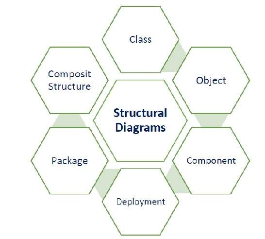
The following table provides a brief description of these diagrams −
| Diagram | Description |
|---|---|
| Class | Represents the object orientation of a system. Shows how classes are statically related. |
| Object | Represents a set of objects and their relationships at runtime and also represent the static view of the system. |
| Component | Describes all the components, their interrelationship, interactions and interface of the system. |
| Composite structure | Describes inner structure of component including all classes, interfaces of the component, etc. |
| Package | Describes the package structure and organization. Covers classes in the package and packages within another package. |
| Deployment | Deployment diagrams are a set of nodes and their relationships. These nodes are physical entities where the components are deployed. |
Behavioral diagrams basically capture the dynamic aspect of a system. Dynamic aspects are basically the changing/moving parts of a system. UML has the following types of behavioral diagrams (shown in the image given below) −
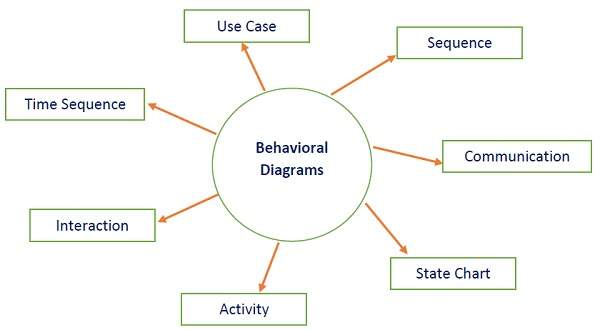
The following table provides a brief description of these diagram −
| Diagram | Description |
|---|---|
| Use case | Describes the relationships among the functionalities and their internal/external controllers. These controllers are known as actors. |
| Activity | Describes the flow of control in a system. It consists of activities and links. The flow can be sequential, concurrent, or branched. |
| State Machine/state chart | Represents the event driven state change of a system. It basically describes the state change of a class, interface, etc. Used to visualize the reaction of a system by internal/external factors. |
| Sequence | Visualizes the sequence of calls in a system to perform a specific functionality. |
| Interaction Overview | Combines activity and sequence diagrams to provide a control flow overview of system and business process. |
| Communication | Same as sequence diagram, except that it focuses on the object’s role. Each communication is associated with a sequence order, number plus the past messages. |
| Time Sequenced | Describes the changes by messages in state, condition and events. |
A model is a complete, basic, and simplified description of software architecture which is composed of multiple views from a particular perspective or viewpoint.
A view is a representation of an entire system from the perspective of a related set of concerns. It is used to describe the system from the viewpoint of different stakeholders such as end-users, developers, project managers, and testers.
The 4+1 View Model was designed by Philippe Kruchten to describe the architecture of a software–intensive system based on the use of multiple and concurrent views. It is a multiple view model that addresses different features and concerns of the system. It standardizes the software design documents and makes the design easy to understand by all stakeholders.
It is an architecture verification method for studying and documenting software architecture design and covers all the aspects of software architecture for all stakeholders. It provides four essential views −
The logical view or conceptual view − It describes the object model of the design.
The process view − It describes the activities of the system, captures the concurrency and synchronization aspects of the design.
The physical view − It describes the mapping of software onto hardware and reflects its distributed aspect.
The development view − It describes the static organization or structure of the software in its development of environment.
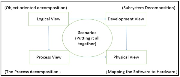
This view model can be extended by adding one more view called scenario view or use case view for end-users or customers of software systems. It is coherent with other four views and are utilized to illustrate the architecture serving as “plus one” view, (4+1) view model. The following figure describes the software architecture using five concurrent views (4+1) model.
The use case view has a special significance as it details the high level requirement of a system while other views details — how those requirements are realized. When all other four views are completed, it’s effectively redundant. However, all other views would not be possible without it. The following image and table shows the 4+1 view in detail −
| Logical | Process | Development | Physical | Scenario | |
|---|---|---|---|---|---|
| Description | Shows the component (Object) of system as well as their interaction | Shows the processes / Workflow rules of system and how those processes communicate, focuses on dynamic view of system | Gives building block views of system and describe static organization of the system modules | Shows the installation, configuration and deployment of software application | Shows the design is complete by performing validation and illustration |
| Viewer / Stake holder | End-User, Analysts and Designer | Integrators & developers | Programmer and software project managers | System engineer, operators, system administrators and system installers | All the views of their views and evaluators |
| Consider | Functional requirements | Non Functional Requirements | Software Module organization (Software management reuse, constraint of tools) | Nonfunctional requirement regarding to underlying hardware | System Consistency and validity |
| UML – Diagram | Class, State, Object, sequence, Communication Diagram | Activity Diagram | Component, Package diagram | Deployment diagram | Use case diagram |
An ADL is a language that provides syntax and semantics for defining a software architecture. It is a notation specification which provides features for modeling a software system’s conceptual architecture, distinguished from the system’s implementation.
ADLs must support the architecture components, their connections, interfaces, and configurations which are the building block of architecture description. It is a form of expression for use in architecture descriptions and provides the ability to decompose components, combine the components, and define the interfaces of components.
An architecture description language is a formal specification language, which describes the software features such as processes, threads, data, and sub-programs as well as hardware component such as processors, devices, buses, and memory.
It is hard to classify or differentiate an ADL and a programming language or a modeling language. However, there are following requirements for a language to be classified as an ADL −
It should be appropriate for communicating the architecture to all concerned parties.
It should be suitable for tasks of architecture creation, refinement, and validation.
It should provide a basis for further implementation, so it must be able to add information to the ADL specification to enable the final system specification to be derived from the ADL.
It should have the ability to represent most of the common architectural styles.
It should support analytical capabilities or provide quick generating prototype implementations.
The object-oriented (OO) paradigm took its shape from the initial concept of a new programming approach, while the interest in design and analysis methods came much later. OO analysis and design paradigm is the logical result of the wide adoption of OO programming languages.
OO is developed over a period of time as −
The first object–oriented language was Simula (Simulation of real systems) that was developed in 1960 by researchers at the Norwegian Computing Center.
In 1970, Alan Kay and his research group at Xerox PARC created a personal computer named Dynabook and the first pure object-oriented programming language (OOPL) - Smalltalk, for programming the Dynabook.
In the 1980s, Grady Booch published a paper titled Object Oriented Design that mainly presented a design for the programming language, Ada. In the ensuing editions, he extended his ideas to a complete object–oriented design method.
In the 1990s, Coad incorporated behavioral ideas to object-oriented methods.
The other significant innovations were Object Modeling Techniques (OMT) by James Rum Baugh and Object-Oriented Software Engineering (OOSE) by Ivar Jacobson.
OO paradigm is a significant methodology for the development of any software. Most of the architecture styles or patterns such as pipe and filter, data repository, and component-based can be implemented by using this paradigm.
Basic concepts and terminologies of object–oriented systems −
An object is a real-world element in an object–oriented environment that may have a physical or a conceptual existence. Each object has −
Identity that distinguishes it from other objects in the system.
State that determines characteristic properties of an object as well as values of properties that the object holds.
Behavior that represents externally visible activities performed by an object in terms of changes in its state.
Objects can be modeled according to the needs of the application. An object may have a physical existence, like a customer, a car, etc.; or an intangible conceptual existence, like a project, a process, etc.
A class represents a collection of objects having same characteristic properties that exhibit common behavior. It gives the blueprint or the description of the objects that can be created from it. Creation of an object as a member of a class is called instantiation. Thus, an object is an instance of a class.
The constituents of a class are −
A set of attributes for the objects that are to be instantiated from the class. Generally, different objects of a class have some difference in the values of the attributes. Attributes are often referred as class data.
A set of operations that portray the behavior of the objects of the class. Operations are also referred as functions or methods.
Example
Let us consider a simple class, Circle, that represents the geometrical figure circle in a two–dimensional space. The attributes of this class can be identified as follows −
Some of its operations can be defined as follows −
Encapsulation is the process of binding both attributes and methods together within a class. Through encapsulation, the internal details of a class can be hidden from outside. It permits the elements of the class to be accessed from outside only through the interface provided by the class.
Polymorphism is originally a Greek word that means the ability to take multiple forms. In object-oriented paradigm, polymorphism implies using operations in different ways, depending upon the instances they are operating upon. Polymorphism allows objects with different internal structures to have a common external interface. Polymorphism is particularly effective while implementing inheritance.
Example
Let us consider two classes, Circle and Square, each with a method findArea(). Though the name and purpose of the methods in the classes are same, the internal implementation, i.e., the procedure of calculating an area is different for each class. When an object of class Circle invokes its findArea() method, the operation finds the area of the circle without any conflict with the findArea() method of the Square class.
Relationships
In order to describe a system, both dynamic (behavioral) and static (logical) specification of a system must be provided. The dynamic specification describes the relationships among objects e.g. message passing. And static specification describe the relationships among classes, e.g. aggregation, association, and inheritance.
Any application requires a number of objects interacting in a harmonious manner. Objects in a system may communicate with each other by using message passing. Suppose a system has two objects − obj1 and obj2. The object obj1 sends a message to object obj2, if obj1 wants obj2 to execute one of its methods.
Aggregation or composition is a relationship among classes by which a class can be made up of any combination of objects of other classes. It allows objects to be placed directly within the body of other classes. Aggregation is referred as a “part–of” or “has–a” relationship, with the ability to navigate from the whole to its parts. An aggregate object is an object that is composed of one or more other objects.
Association is a group of links having common structure and common behavior. Association depicts the relationship between objects of one or more classes. A link can be defined as an instance of an association. The Degree of an association denotes the number of classes involved in a connection. The degree may be unary, binary, or ternary.
It is a mechanism that permits new classes to be created out of existing classes by extending and refining its capabilities. The existing classes are called the base classes/parent classes/super-classes, and the new classes are called the derived classes/child classes/subclasses.
The subclass can inherit or derive the attributes and methods of the super-class (es) provided that the super-class allows so. Besides, the subclass may add its own attributes and methods and may modify any of the super-class methods. Inheritance defines a “is – a” relationship.
Example
From a class Mammal, a number of classes can be derived such as Human, Cat, Dog, Cow, etc. Humans, cats, dogs, and cows all have the distinct characteristics of mammals. In addition, each has its own particular characteristics. It can be said that a cow “is – a” mammal.
In object-oriented analysis phase of software development, the system requirements are determined, the classes are identified, and the relationships among classes are acknowledged. The aim of OO analysis is to understand the application domain and specific requirements of the system. The result of this phase is requirement specification and initial analysis of logical structure and feasibility of a system.
The three analysis techniques that are used in conjunction with each other for object-oriented analysis are object modeling, dynamic modeling, and functional modeling.
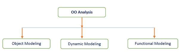
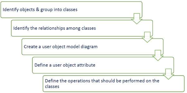
Object modeling develops the static structure of the software system in terms of objects. It identifies the objects, the classes into which the objects can be grouped into and the relationships between the objects. It also identifies the main attributes and operations that characterize each class.
The process of object modeling can be visualized in the following steps −
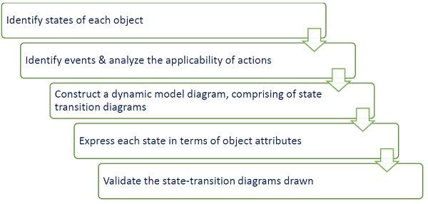
After the static behavior of the system is analyzed, its behavior with respect to time and external changes needs to be examined. This is the purpose of dynamic modeling.
Dynamic Modeling can be defined as “a way of describing how an individual object responds to events, either internal events triggered by other objects, or external events triggered by the outside world.”
The process of dynamic modeling can be visualized in the following steps −
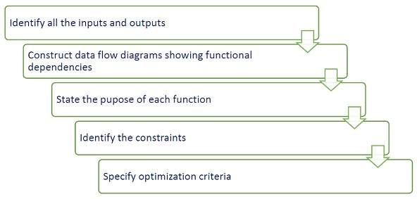
Functional Modeling is the final component of object-oriented analysis. The functional model shows the processes that are performed within an object and how the data changes, as it moves between methods. It specifies the meaning of the operations of an object modeling and the actions of a dynamic modeling. The functional model corresponds to the data flow diagram of traditional structured analysis.
The process of functional modeling can be visualized in the following steps −
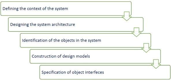
After the analysis phase, the conceptual model is developed further into an object-oriented model using object-oriented design (OOD). In OOD, the technology-independent concepts in the analysis model are mapped onto implementing classes, constraints are identified, and interfaces are designed, resulting in a model for the solution domain. The main aim of OO design is to develop the structural architecture of a system.
The stages for object–oriented design can be identified as −
OO Design can be divided into two stages − Conceptual design and Detailed design.
Conceptual design
In this stage, all the classes are identified that are needed for building the system. Further, specific responsibilities are assigned to each class. Class diagram is used to clarify the relationships among classes, and interaction diagram are used to show the flow of events. It is also known as high-level design.
Detailed design
In this stage, attributes and operations are assigned to each class based on their interaction diagram. State machine diagram are developed to describe the further details of design. It is also known as low-level design.
Following are the major design principles −
Principle of Decoupling
It is difficult to maintain a system with a set of highly interdependent classes, as modification in one class may result in cascading updates of other classes. In an OO design, tight coupling can be eliminated by introducing new classes or inheritance.
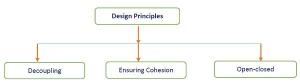
Ensuring Cohesion
A cohesive class performs a set of closely related functions. A lack of cohesion means — a class performs unrelated functions, although it does not affect the operation of the whole system. It makes the entire structure of software hard to manage, expand, maintain, and change.
Open-closed Principle
According to this principle, a system should be able to extend to meet the new requirements. The existing implementation and the code of the system should not be modified as a result of a system expansion. In addition, the following guidelines have to be followed in open-closed principle −
For each concrete class, separate interface and implementations have to be maintained.
In a multithreaded environment, keep the attributes private.
Minimize the use of global variables and class variables.
In data flow architecture, the whole software system is seen as a series of transformations on consecutive pieces or set of input data, where data and operations are independent of each other. In this approach, the data enters into the system and then flows through the modules one at a time until they are assigned to some final destination (output or a data store).
The connections between the components or modules may be implemented as I/O stream, I/O buffers, piped, or other types of connections. The data can be flown in the graph topology with cycles, in a linear structure without cycles, or in a tree type structure.
The main objective of this approach is to achieve the qualities of reuse and modifiability. It is suitable for applications that involve a well-defined series of independent data transformations or computations on orderly defined input and output such as compilers and business data processing applications. There are three types of execution sequences between modules−
Batch sequential is a classical data processing model, in which a data transformation subsystem can initiate its process only after its previous subsystem is completely through −
The flow of data carries a batch of data as a whole from one subsystem to another.
The communications between the modules are conducted through temporary intermediate files which can be removed by successive subsystems.
It is applicable for those applications where data is batched, and each subsystem reads related input files and writes output files.
Typical application of this architecture includes business data processing such as banking and utility billing.
Normally, Batch Sequential provides simpler divisions on subsystems. Each subsystem can be an independent program working on input data and producing output data.
Does not provide concurrency and interactive interface rather it provides high latency and low throughput. Further, external control is required for the implementation.
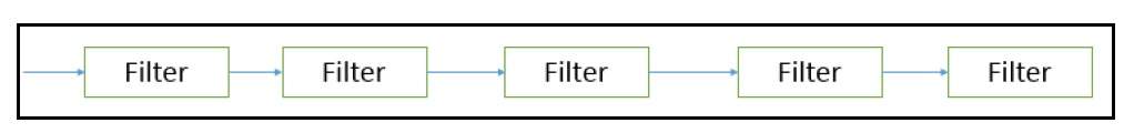
This approach lays emphasis on the incremental transformation of data by successive component. In this approach, the flow of data is driven by data and the whole system is decomposed into components of data source, filters, pipes, and data sinks.
The connections between modules are data stream which is first-in/first-out buffer that can be stream of bytes, characters, or any other type of such kind. The main feature of this architecture is its concurrent and incremented execution.
A filter is an independent data stream transformer or stream transducers. It transforms the data of the input data stream, processes it, and writes the transformed data stream over a pipe for the next filter to process. It works in an incremental mode, in which it starts working as soon as data arrives through connected pipe. There are two types of filters − active filter/ and passive filter.
Active filter
Active filter lets connected pipes to pull data in and push out the transformed data. It operates with passive pipe, which provides read/write mechanisms for pulling and pushing. This mode is used in UNIX pipe and filter mechanism.
Passive filter
Passive filter lets connected pipes to push data in and pull data out. It operates with active pipe, which pulls data from a filter and pushes data into the next filter. It must provide read/write mechanism.
It has following advantages −
Provides concurrency and high throughput for excessive data processing.
Provides reusability and simplifies system maintenance.
Provides modifiability and low coupling between filters.
Provides simplicity by offering clear divisions between any two filters connected by pipe.
Provides flexibility by supporting both sequential and parallel execution.
It has some of the following disadvantages −
Not suitable for dynamic interactions.
A low common denominator is needed for transmission of data in ASCII formats.
Overhead of data transformation between filters.
Does not provide a way for filters to cooperatively interact to solve a problem.
Difficult to configure this architecture dynamically.
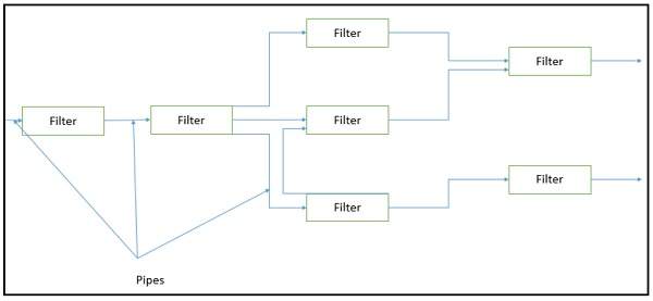
Pipes are stateless and they carry binary or character stream which exist between two filters. It can move a data stream from one filter to another. Pipes use a little contextual information and retain no state information between instantiations.
It is a type of data flow architecture where data is neither batched sequential nor pipelined stream. The flow of data comes from a set of variables, which controls the execution of process. It decomposes the entire system into subsystems or modules and connects them.
A process control architecture would have a processing unit for changing the process control variables and a controller unit for calculating the amount of changes.
A controller unit must have the following elements −
Controlled Variable − Controlled Variable provides values for the underlying system and should be measured by sensors. For example, speed in cruise control system.
Input Variable − Measures an input to the process. For example, temperature of return air in temperature control system
Manipulated Variable − Manipulated Variable value is adjusted or changed by the controller.
Process Definition − It includes mechanisms for manipulating some process variables.
Sensor − Obtains values of process variables pertinent to control and can be used as a feedback reference to recalculate manipulated variables.
Set Point − It is the desired value for a controlled variable.
Control Algorithm − It is used for deciding how to manipulate process variables.
Process control architecture is suitable in the following domains −
Embedded system software design, where the system is manipulated by process control variable data.
Applications, which aim is to maintain specified properties of the outputs of the process at given reference values.
Applicable for car-cruise control and building temperature control systems.
Real-time system software to control automobile anti-lock brakes, nuclear power plants, etc.
In data-centered architecture, the data is centralized and accessed frequently by other components, which modify data. The main purpose of this style is to achieve integrality of data. Data-centered architecture consists of different components that communicate through shared data repositories. The components access a shared data structure and are relatively independent, in that, they interact only through the data store.
The most well-known examples of the data-centered architecture is a database architecture, in which the common database schema is created with data definition protocol – for example, a set of related tables with fields and data types in an RDBMS.
Another example of data-centered architectures is the web architecture which has a common data schema (i.e. meta-structure of the Web) and follows hypermedia data model and processes communicate through the use of shared web-based data services.
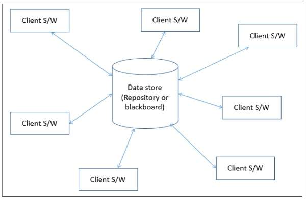
There are two types of components −
A central data structure or data store or data repository, which is responsible for providing permanent data storage. It represents the current state.
A data accessor or a collection of independent components that operate on the central data store, perform computations, and might put back the results.
Interactions or communication between the data accessors is only through the data store. The data is the only means of communication among clients. The flow of control differentiates the architecture into two categories as Repository Architecture Style and Blackboard Architecture Style. A brief detail about both the categories is given below −
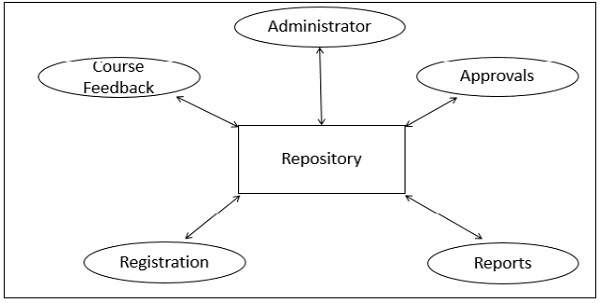
In Repository Architecture Style, the data store is passive and the clients (software components or agents) of the data store are active, which control the logic flow. The participating components check the data-store for changes.
A client sends a request to the system to perform actions (e.g. insert data). The computational processes are independent and triggered by incoming requests. If the types of transactions in an input stream of transactions trigger selection of processes to execute, then it is traditional database or repository architecture, or passive repository. This approach is widely used in DBMS, library information system, the interface repository in CORBA, compilers, and CASE (computer aided software engineering) environments.
Repository Architecture Style has following advantages −
Provides data integrity, backup and restore features.
Provides scalability and reusability of agents as they do not have direct communication with each other.
Reduces overhead of transient data between software components.
Because of being more vulnerable to failure and data replication or duplication, Repository Architecture Style has following disadvantages −
High dependency between data structure of data store and its agents.
Changes in data structure highly affect the clients.
Evolution of data is difficult and expensive.
Cost of moving data on network for distributed data.
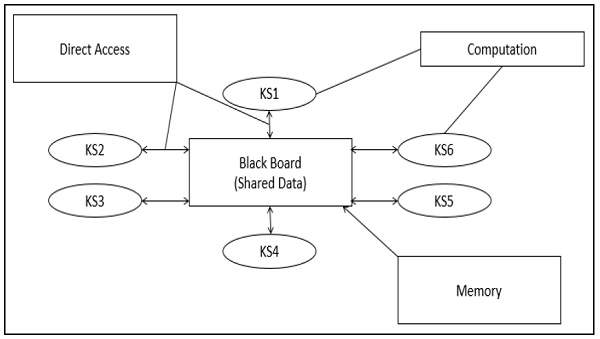
In Blackboard Architecture Style, the data store is active and its clients are passive. Therefore the logical flow is determined by the current data status in data store. It has a blackboard component, acting as a central data repository, and an internal representation is built and acted upon by different computational elements.
Further, a number of components that act independently on the common data structure are stored in the blackboard. In this style, the components interact only through the blackboard. The data-store alerts the clients whenever there is a data-store changes. The current state of the solution is stored in the blackboard and processing is triggered by the state of the blackboard.
When changes occur in the data, the system sends the notifications known as trigger and data to the clients. This approach is found in certain AI applications and complex applications, such as speech recognition, image recognition, security system, and business resource management systems etc.
If the current state of the central data structure is the main trigger of selecting processes to execute, the repository can be a blackboard and this shared data source is an active agent.
A major difference with traditional database systems is that the invocation of computational elements in a blackboard architecture is triggered by the current state of the blackboard, and not by external inputs.
The blackboard model is usually presented with three major parts −
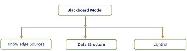
Knowledge Sources, also known as Listeners or Subscribers are distinct and independent units. They solve parts of a problem and aggregate partial results. Interaction among knowledge sources takes place uniquely through the blackboard.
The problem-solving state data is organized into an application-dependent hierarchy. Knowledge sources make changes to the blackboard that lead incrementally to a solution to the problem.
Control manages tasks and checks the work state.
Blackboard Model provides concurrency that allows all knowledge sources to work in parallel as they independent of each other. Its scalability feature facilitates easy steps to add or update knowledge source. Further, it supports experimentation for hypotheses and reusability of knowledge source agents.
The structural change of blackboard may have a significant impact on all of its agents, as close dependency exists between blackboard and knowledge source. Blackboard model is expected to produce approximate solution; however, sometimes, it becomes difficult to decide when to terminate the reasoning.
Further, this model suffers some problems in synchronization of multiple agents, therefore, it faces challenge in designing and testing of the system.
Hierarchical architecture views the whole system as a hierarchy structure, in which the software system is decomposed into logical modules or subsystems at different levels in the hierarchy. This approach is typically used in designing system software such as network protocols and operating systems.
In system software hierarchy design, a low-level subsystem gives services to its adjacent upper level subsystems, which invoke the methods in the lower level. The lower layer provides more specific functionality such as I/O services, transaction, scheduling, security services, etc. The middle layer provides more domain dependent functions such as business logic and core processing services. And, the upper layer provides more abstract functionality in the form of user interface such as GUIs, shell programming facilities, etc.
It is also used in organization of the class libraries such as .NET class library in namespace hierarchy. All the design types can implement this hierarchical architecture and often combine with other architecture styles.
Hierarchical architectural styles is divided as −
The aim of this style is to reuse the modules and freely develop individual modules or subroutine. In this style, a software system is divided into subroutines by using top-down refinement according to desired functionality of the system.
These refinements lead vertically until the decomposed modules is simple enough to have its exclusive independent responsibility. Functionality may be reused and shared by multiple callers in the upper layers.
There are two ways by which data is passed as parameters to subroutines, namely −
Pass by Value − Subroutines only use the past data, but can’t modify it.
Pass by Reference &minu; Subroutines use as well as change the value of the data referenced by the parameter.
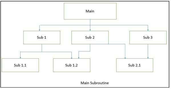
Significant advantages of Main-subroutine are — it is easy to decompose the system based on hierarchy refinement. Further, it can be also used in a subsystem of object oriented design.
Main-subroutine has some disadvantages such as tight coupling may cause more ripple effects of changes. Secondly, it contains globally shared data, so it is also vulnerable.
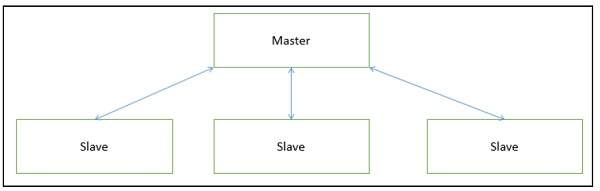
This approach applies the 'divide and conquer' principle and supports fault computation and computational accuracy. It is a modification of the main-subroutine architecture that provides reliability of system and fault tolerance.
In this architecture, slaves provide duplicat services to the master, and the master chooses a particular result among slaves by a certain selection strategy. The slaves may perform the same functional task by different algorithms and methods or totally different functionality. It includes parallel computing in which all the slaves can be executed in parallel.
The implementation of the Master-Slave pattern follows five steps −
Step 1 − Specify how the computation of the task can be divided into a set of equal sub-tasks and identify the sub-services that are needed to process a sub-task.
Step 2 − Specify how the final result of the whole service can be computed with the help of the results obtained from processing individual sub-tasks.
Step 3 − Define an interface for the sub-service identified in step 1. It will be implemented by the slave and used by the master to delegate the processing of individual sub-tasks.
Step 4 − Implement the slave components according to the specifications developed in the previous step.
Step 5 − Implement the master according to the specifications developed in step 1 to 3.
Virtual Machine architecture pretends some functionality, which is not native to the hardware and/or software on which it is implemented. A virtual machine is built upon an existing system and provides a virtual abstraction, a set of attributes, and operations.
In virtual machine architecture, the master uses the ‘same’ subservice’ from the slave and performs functions such as split work, call slaves, and combine results. It allows developers to simulate and test platforms, which have not yet been built, and simulate "disaster'' modes that would be too complex, costly, or dangerous to test with the real system.
In most cases, a virtual machine splits a programming language or application environment from an execution platform. The main objective is to provide portability. Interpretation of a particular module via a Virtual Machine may be perceived as −
The interpretation engine chooses an instruction from the module being interpreted.
Based on the instruction, the engine updates the virtual machine’s internal state and the above process is repeated.
The following figure shows the architecture of a standard VM infrastructure on a single physical machine.
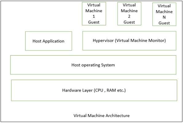
The hypervisor, also called the virtual machine monitor, runs on the host OS and allocates matched resources to each guest OS. When the guest makes a system-call, the hypervisor intercepts and translates it into the corresponding system-call supported by the host OS. The hypervisor controls each virtual machine access to the CPU, memory, persistent storage, I/O devices, and the network.
Virtual machine architecture is suitable in the following domains −
Suitable for solving a problem by simulation or translation if there is no direct solution.
Sample applications include interpreters of microprogramming, XML processing, script command language execution, rule-based system execution, Smalltalk and Java interpreter typed programming language.
Common examples of virtual machines are interpreters, rule-based systems, syntactic shells, and command language processors.
Because of having the features of portability and machine platform independency, it has following advantages −
In this approach, the system is decomposed into a number of higher and lower layers in a hierarchy, and each layer has its own sole responsibility in the system.
Each layer consists of a group of related classes that are encapsulated in a package, in a deployed component, or as a group of subroutines in the format of method library or header file.
Each layer provides service to the layer above it and serves as a client to the layer below i.e. request to layer i +1 invokes the services provided by the layer i via the interface of layer i. The response may go back to the layer i +1 if the task is completed; otherwise layer i continually invokes services from layer i -1 below.
Layered style is suitable in the following areas −
Applications that involve distinct classes of services that can be organized hierarchically.
Any application that can be decomposed into application-specific and platform-specific portions.
Applications that have clear divisions between core services, critical services, and user interface services, etc.
It has following advantages −
Design based on incremental levels of abstraction.
Provides enhancement independence as changes to the function of one layer affects at most two other layers.
Separation of the standard interface and its implementation.
Implemented by using component-based technology which makes the system much easier to allow for plug-and-play of new components.
Each layer can be an abstract machine deployed independently which support portability.
Easy to decompose the system based on the definition of the tasks in a top-down refinement manner
Different implementations (with identical interfaces) of the same layer can be used interchangeably
Since, many applications or systems are not easily structured in a layered fashion, so it has following disadvantages −
Lower runtime performance since a client’s request or a response to client must go through potentially several layers.
There are also performance concerns on overhead on the data marshaling and buffering by each layer.
Opening of interlayer communication may cause deadlocks and “bridging” may cause tight coupling.
Exceptions and error handling is an issue in the layered architecture, since faults in one layer must spread upwards to all calling layers
The primary objective of interaction-oriented architecture is to separate the interaction of user from data abstraction and business data processing. The interaction-oriented software architecture decomposes the system into three major partitions −
Data module − Data module provides the data abstraction and all business logic.
Control module − Control module identifies the flow of control and system configuration actions.
View presentation module − View presentation module is responsible for visual or audio presentation of data output and it also provides an interface for user input.
Interaction-oriented architecture has two major styles − Model-View-Controller (MVC) and Presentation-Abstraction-Control (PAC). Both MVC and PAC propose three components decomposition and are used for interactive applications such as web applications with multiple talks and user interactions. They are different in their flow of control and organization. PAC is an agent-based hierarchical architecture but MVC does not have a clear hierarchical structure.
MVC decomposes a given software application into three interconnected parts that help in separating the internal representations of information from the information presented to or accepted from the user.
| Module | Function |
|---|---|
| Model | Encapsulation the underlying data and business logic |
| Controller | Respond to user action and direct the application flow |
| View | Formats and present the data from model to user. |
Model is a central component of MVC that directly manages the data, logic, and constraints of an application. It consists of data components, which maintain the raw application data and application logic for interface.
It is an independent user interface and captures the behavior of application problem domain. Model is the domain-specific software simulation or implementation of the application's central structure.
If there is change in its state, it gives notification to its associated view to produce updated output, and the controller to change the available set of commands.
A controller accepts an input and converts it into commands for the model or view. It acts as an interface between the associated models and views and the input devices.
Controller can send commands to the model to update the model’s state and to its associated view to change the view’s presentation of the model. Likewise, as shown in the picture given below, it consists of input processing components, which handle input from the user by modifying the model.
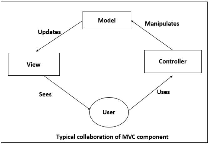
View can be used to represent any output of information in graphical form such as diagram or chart. It consists of presentation components which provide the visual representations of data.
Views request information from their model and generate an output representation to the user. Multiple views of the same information are possible, such as a bar chart for management and a tabular view for accountants.
It is a simple version of MVC architecture where the system is divided into two sub-systems −
The Controller-View − The controller-view acts as input /output interface and processing is done.
The Model − The model provides all the data and domain services.
MVC-I Architecture
The model module notifies controller-view module of any data changes so that any graphics data display will be changed accordingly. The controller also takes appropriate action upon the changes.
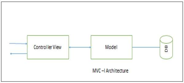
The connection between controller-view and model can be designed in a pattern (as shown in the above picture) of subscribe-notify whereby the controller-view subscribes to model and model notifies controller-view of any changes.
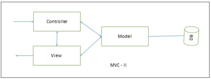
MVC–II is an enhancement of MVC-I architecture in which the view module and the controller module are separate. The model module plays an active role as in MVC-I by providing all the core functionality and data supported by database.
The view module presents data while controller module accepts input request, validates input data, initiates the model, the view, their connection, and also dispatches the task.
MVC-II Architecture
MVC applications are effective for interactive applications where multiple views are needed for a single data model and easy to plug-in a new or change interface view.
MVC applications are suitable for applications where there are clear divisions between the modules so that different professionals can be assigned to work on different aspects of such applications concurrently.
Advantages
Because of having multiple MVC vendor framework toolkits, it has following advantages −
Multiple views synchronized with same data model.
Easy to plug-in new or replace interface views.
Used for application development where graphics expertise professionals, programming professionals, and data base development professionals are working in a designed project team.
Disadvantages
Not suitable for agent-oriented applications such as interactive mobile and robotics applications.
Multiple pairs of controllers and views based on the same data model make any data model change expensive.
The division between the View and the Controller is not clear in some cases.
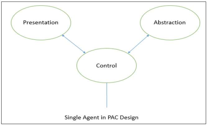
In PAC, the system is arranged into a hierarchy of many cooperating agents (triads). It was developed from MVC to support the application requirement of multiple agents in addition to interactive requirements.
Each agent has three components −
The presentation component − Formats the visual and audio presentation of data.
The abstraction component − Retrieves and processes the data.
The control component − Handles the task such as the flow of control and communication between the other two components.
The PAC architecture is similar to MVC, in the sense that presentation module is like view module of MVC. The abstraction module looks like model module of MVC and the control module is like the controller module of MVC, but they differ in their flow of control and organization.
There are no direct connections between abstraction component and presentation component in each agent. The control component in each agent is in charge of communications with other agents.
The following figure shows a block diagram for a single agent in PAC design.
As shown in the following image, in PACs consisting of multiple agents, the top-level agent provides core data and business logics. The bottom level agents define detailed specific data and presentations. The intermediate level or middle level agent acts as coordinator of low-level agents.
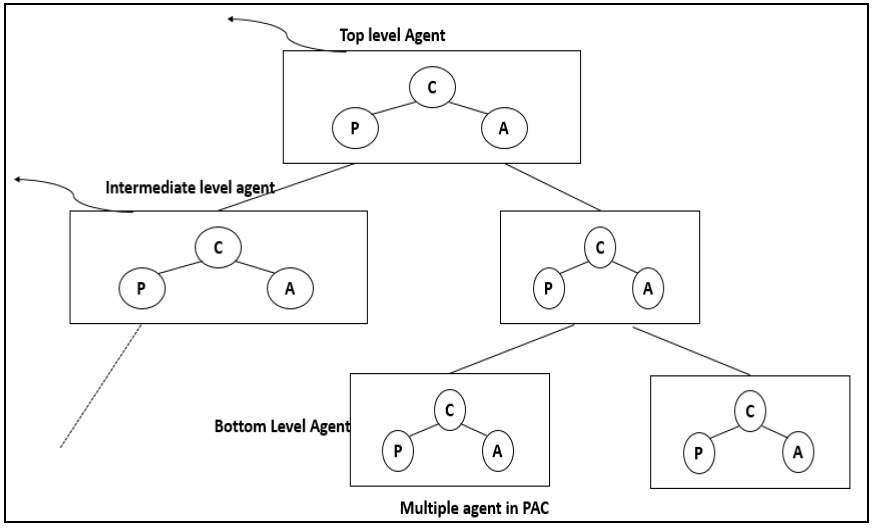
Each agent has its own specific assigned job. For some middle level agents the interactive presentations are not required, so they do not have a presentation component. The control component is required for all agents through which all the agents communicate with each other.
Applications
Effective for an interactive system where the system can be decomposed into many cooperating agents in a hierarchical manner.
Effective when the coupling among the agents is expected to be loose so that changes on an agent does not affect others.
Effective for distributed system where all the agents are distantly distributed and each of them has its own functionalities with data and interactive interface.
Suitable for applications with rich GUI components where each of them keeps its own current data and interactive interface and needs to communicate with other components.
Support for multi-tasking and multi-viewing
Support for agent reusability and extensibility
Easy to plug-in new agent or change an existing one
Support for concurrency where multiple agents are running in parallel in different threads or different devices or computers
Overhead due to the control bridge between presentation and abstraction and the communication of controls among agents.
Difficult to determine the right number of agents because of loose coupling and high independence among agents.
In distributed architecture, components are presented on different platforms and several components can cooperate with one another over a communication network in order to achieve a specific objective or goal.
A distributed system can be demonstrated by the client-server architecture, which forms the base for multi-tier architectures; alternatives are the broker architecture such as CORBA, and the Service-Oriented Architecture (SOA). In this architecture, information processing is not confined to a single machine rather it is distributed over several independent computers.
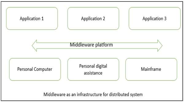
There are several technology frameworks to support distributed architectures, including .NET, J2EE, CORBA, .NET Web services, AXIS Java Web services, and Globus Grid services. Middleware is an infrastructure that appropriately supports the development and execution of distributed applications. It provides a buffer between the applications and the network.
It sits in the middle of system and manages or supports the different components of a distributed system. Examples are transaction processing monitors, data convertors and communication controllers, etc.
Middleware as an infrastructure for distributed system −
The basis of a distributed architecture is its transparency, reliability, and availability.
The following table lists the different forms of transparency in a distributed system −
| Transparency | Description |
|---|---|
| Access | Hides the way in which resources are accessed and the differences in data platform. |
| Location | Hides where resources are located. |
| Technology | Hides different technologies such as programming language and OS from user. |
| Migration / Relocation | Hide resources that may be moved to another location which are in use. |
| Replication | Hide resources that may be copied at several location. |
| Concurrency | Hide resources that may be shared with other users. |
| Failure | Hides failure and recovery of resources from user. |
| Persistence | Hides whether a resource ( software ) is in memory or disk. |
It has following advantages −
Resource sharing − Sharing of hardware and software resources.
Openness − Flexibility of using hardware and software of different vendors.
Concurrency − Concurrent processing to enhance performance.
Scalability − Increased throughput by adding new resources.
Fault tolerance − The ability to continue in operation after a fault has occurred.
Its disadvantages are −
Complexity − They are more complex than centralized systems.
Security − More susceptible to external attack.
Manageability − More effort required for system management.
Unpredictability − Unpredictable responses depending on the system organization and network load.
| Criteria | Centralized system | Distributed System |
|---|---|---|
| Economics | Low | High |
| Availability | Low | High |
| Complexity | Low | High |
| Consistency | Simple | High |
| Scalability | Poor | Good |
| Technology | Homogeneous | Heterogeneous |
| Security | High | Low |
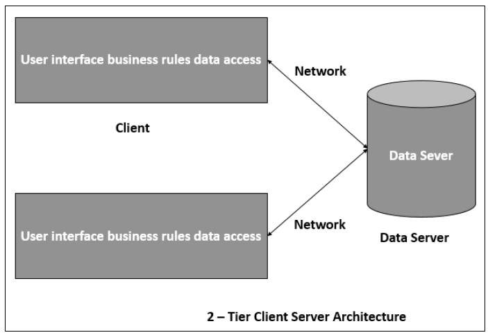
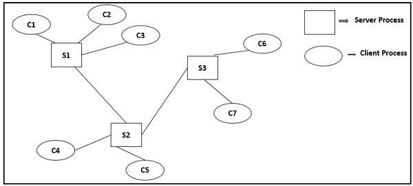
The client-server architecture is the most common distributed system architecture which decomposes the system into two major subsystems or logical processes −
Client − This is the first process that issues a request to the second process i.e. the server.
Server − This is the second process that receives the request, carries it out, and sends a reply to the client.
In this architecture, the application is modelled as a set of services those are provided by servers and a set of clients that use these services. The servers need not to know about clients, but the clients must know the identity of servers.
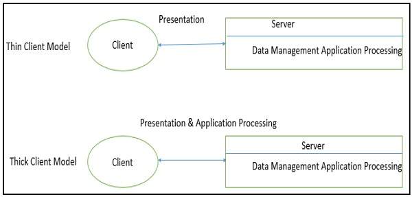
Client-server Architecture can be classified into two models based on the functionality of the client −
In thin-client model, all the application processing and data management is carried by the server. The client is simply responsible for running the GUI software. It is used when legacy systems are migrated to client server architectures in which legacy system acts as a server in its own right with a graphical interface implemented on a client.
However, A major disadvantage is that it places a heavy processing load on both the server and the network.
In thick-client model, the server is in-charge of the data management. The software on the client implements the application logic and the interactions with the system user. It is most appropriate for new client-server systems where the capabilities of the client system are known in advance.
However, it is more complex than a thin client model especially for management, as all clients should have same copy/version of software application.
Separation of responsibilities such as user interface presentation and business logic processing.
Reusability of server components and potential for concurrency
Simplifies the design and the development of distributed applications
It makes it easy to migrate or integrate existing applications into a distributed environment.
It also makes effective use of resources when a large number of clients are accessing a high-performance server.
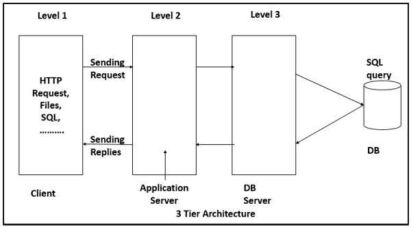
Multi-tier architecture is a client–server architecture in which the functions such as presentation, application processing, and data management are physically separated. By separating an application into tiers, developers obtain the option of changing or adding a specific layer, instead of reworking the entire application. It provides a model by which developers can create flexible and reusable applications.
The most general use of multi-tier architecture is the three-tier architecture. A three-tier architecture is typically composed of a presentation tier, an application tier, and a data storage tier and may execute on a separate processor.
Presentation layer is the topmost level of the application by which users can access directly such as webpage or Operating System GUI (Graphical User interface). The primary function of this layer is to translate the tasks and results to something that user can understand. It communicates with other tiers so that it places the results to the browser/client tier and all other tiers in the network.
Application tier coordinates the application, processes the commands, makes logical decisions, evaluation, and performs calculations. It controls an application’s functionality by performing detailed processing. It also moves and processes data between the two surrounding layers.
In this layer, information is stored and retrieved from the database or file system. The information is then passed back for processing and then back to the user. It includes the data persistence mechanisms (database servers, file shares, etc.) and provides API (Application Programming Interface) to the application tier which provides methods of managing the stored data.
Advantages
Better performance than a thin-client approach and is simpler to manage than a thick-client approach.
Enhances the reusability and scalability − as demands increase, extra servers can be added.
Provides multi-threading support and also reduces network traffic.
Provides maintainability and flexibility
Disadvantages
Broker Architectural Style is a middleware architecture used in distributed computing to coordinate and enable the communication between registered servers and clients. Here, object communication takes place through a middleware system called an object request broker (software bus).
However, client and the server do not interact with each other directly. Client and server have a direct connection to its proxy, which communicates with the mediator-broker. A server provides services by registering and publishing their interfaces with the broker and clients can request the services from the broker statically or dynamically by look-up.
CORBA (Common Object Request Broker Architecture) is a good implementation example of the broker architecture.
The components of broker architectural style are discussed through following heads −
Broker
Broker is responsible for coordinating communication, such as forwarding and dispatching the results and exceptions. It can be either an invocation-oriented service, a document or message - oriented broker to which clients send a message.
Broker is responsible for brokering the service requests, locating a proper server, transmitting requests, and sending responses back to clients. It also retains the servers’ registration information including their functionality and services as well as location information.
Further, it provides APIs for clients to request, servers to respond, registering or unregistering server components, transferring messages, and locating servers.
Stub
Stubs are generated at the static compilation time and then deployed to the client side which is used as a proxy for the client. Client-side proxy acts as a mediator between the client and the broker and provides additional transparency between them and the client; a remote object appears like a local one.
The proxy hides the IPC (inter-process communication) at protocol level and performs marshaling of parameter values and un-marshaling of results from the server.
Skeleton
Skeleton is generated by the service interface compilation and then deployed to the server side, which is used as a proxy for the server. Server-side proxy encapsulates low-level system-specific networking functions and provides high-level APIs to mediate between the server and the broker.
Further, it receives the requests, unpacks the requests, unmarshals the method arguments, calls the suitable service, and also marshals the result before sending it back to the client.
Bridge
A bridge can connect two different networks based on different communication protocols. It mediates different brokers including DCOM, .NET remote, and Java CORBA brokers.
Bridges are optional component, which hides the implementation details when two brokers interoperate and take requests and parameters in one format and translate them to another format.
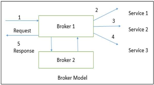
Broker implementation in CORBA
CORBA is an international standard for an Object Request Broker – a middleware to manage communications among distributed objects defined by OMG (object management group).
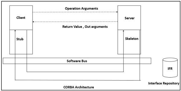
A service is a component of business functionality that is well-defined, self-contained, independent, published, and available to be used via a standard programming interface. The connections between services are conducted by common and universal message-oriented protocols such as the SOAP Web service protocol, which can deliver requests and responses between services loosely.
Service-oriented architecture is a client/server design which support business-driven IT approach in which an application consists of software services and software service consumers (also known as clients or service requesters).
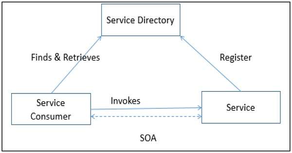
A service-oriented architecture provides the following features −
Distributed Deployment − Expose enterprise data and business logic as loosely, coupled, discoverable, structured, standard-based, coarse-grained, stateless units of functionality called services.
Composability − Assemble new processes from existing services that are exposed at a desired granularity through well defined, published, and standard complaint interfaces.
Interoperability − Share capabilities and reuse shared services across a network irrespective of underlying protocols or implementation technology.
Reusability − Choose a service provider and access to existing resources exposed as services.
The following figure illustrates how does SOA operate −
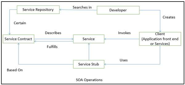
Advantages
Loose coupling of service–orientation provides great flexibility for enterprises to make use of all available service recourses irrespective of platform and technology restrictions.
Each service component is independent from other services due to the stateless service feature.
The implementation of a service will not affect the application of the service as long as the exposed interface is not changed.
A client or any service can access other services regardless of their platform, technology, vendors, or language implementations.
Reusability of assets and services since clients of a service only need to know its public interfaces, service composition.
SOA based business application development are much more efficient in terms of time and cost.
Enhances the scalability and provide standard connection between systems.
Efficient and effective usage of ‘Business Services’.
Integration becomes much easier and improved intrinsic interoperability.
Abstract complexity for developers and energize business processes closer to end users.
Component-based architecture focuses on the decomposition of the design into individual functional or logical components that represent well-defined communication interfaces containing methods, events, and properties. It provides a higher level of abstraction and divides the problem into sub-problems, each associated with component partitions.
The primary objective of component-based architecture is to ensure component reusability. A component encapsulates functionality and behaviors of a software element into a reusable and self-deployable binary unit. There are many standard component frameworks such as COM/DCOM, JavaBean, EJB, CORBA, .NET, web services, and grid services. These technologies are widely used in local desktop GUI application design such as graphic JavaBean components, MS ActiveX components, and COM components which can be reused by simply drag and drop operation.
Component-oriented software design has many advantages over the traditional object-oriented approaches such as −
Reduced time in market and the development cost by reusing existing components.
Increased reliability with the reuse of the existing components.
A component is a modular, portable, replaceable, and reusable set of well-defined functionality that encapsulates its implementation and exporting it as a higher-level interface.
A component is a software object, intended to interact with other components, encapsulating certain functionality or a set of functionalities. It has an obviously defined interface and conforms to a recommended behavior common to all components within an architecture.
A software component can be defined as a unit of composition with a contractually specified interface and explicit context dependencies only. That is, a software component can be deployed independently and is subject to composition by third parties.
A component can have three different views − object-oriented view, conventional view, and process-related view.
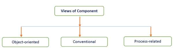
Object-oriented view
A component is viewed as a set of one or more cooperating classes. Each problem domain class (analysis) and infrastructure class (design) are explained to identify all attributes and operations that apply to its implementation. It also involves defining the interfaces that enable classes to communicate and cooperate.
Conventional view
It is viewed as a functional element or a module of a program that integrates the processing logic, the internal data structures that are required to implement the processing logic and an interface that enables the component to be invoked and data to be passed to it.
Process-related view
In this view, instead of creating each component from scratch, the system is building from existing components maintained in a library. As the software architecture is formulated, components are selected from the library and used to populate the architecture.
A user interface (UI) component includes grids, buttons referred as controls, and utility components expose a specific subset of functions used in other components.
Other common types of components are those that are resource intensive, not frequently accessed, and must be activated using the just-in-time (JIT) approach.
Many components are invisible which are distributed in enterprise business applications and internet web applications such as Enterprise JavaBean (EJB), .NET components, and CORBA components.
Reusability − Components are usually designed to be reused in different situations in different applications. However, some components may be designed for a specific task.
Replaceable − Components may be freely substituted with other similar components.
Not context specific − Components are designed to operate in different environments and contexts.
Extensible − A component can be extended from existing components to provide new behavior.
Encapsulated − A A component depicts the interfaces, which allow the caller to use its functionality, and do not expose details of the internal processes or any internal variables or state.
Independent − Components are designed to have minimal dependencies on other components.
A component-level design can be represented by using some intermediary representation (e.g. graphical, tabular, or text-based) that can be translated into source code. The design of data structures, interfaces, and algorithms should conform to well-established guidelines to help us avoid the introduction of errors.
It has following salient features −
The software system is decomposed into reusable, cohesive, and encapsulated component units.
Each component has its own interface that specifies required ports and provided ports; each component hides its detailed implementation.
A component should be extended without the need to make internal code or design modifications to the existing parts of the component.
Depend on abstractions component do not depend on other concrete components, which increase difficulty in expendability.
Connectors connected components, specifying and ruling the interaction among components. The interaction type is specified by the interfaces of the components.
Components interaction can take the form of method invocations, asynchronous invocations, broadcasting, message driven interactions, data stream communications, and other protocol specific interactions.
For a server class, specialized interfaces should be created to serve major categories of clients. Only those operations that are relevant to a particular category of clients should be specified in the interface.
A component can extend to other components and still offer its own extension points. It is the concept of plug-in based architecture. This allows a plugin to offer another plugin API.
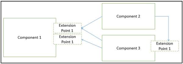
It creates a naming conventions for components that are specified as part of the architectural model and then refines or elaborates as part of the component-level model.
Attains architectural component names from the problem domain and ensures that they have meaning to all stakeholders who view the architectural model.
Extracts the business process entities that can exist independently without any associated dependency on other entities.
Recognizes and discover these independent entities as new components.
Uses infrastructure component names that reflect their implementation-specific meaning.
Models any dependencies from left to right and inheritance from top (base class) to bottom (derived classes).
Model any component dependencies as interfaces rather than representing them as a direct component-to-component dependency.
It recognizes all design classes that correspond to the problem domain as defined in the analysis model and architectural model.
This design has following important features −
Recognizes all design classes that correspond to the infrastructure domain.
Describes all design classes that are not acquired as reusable components, and specifies message details.
Identifies appropriate interfaces for each component and elaborates attributes and defines data types and data structures required to implement them.
Describes processing flow within each operation in detail by means of pseudo code or UML activity diagrams.
Describes persistent data sources (databases and files) and identifies the classes required to manage them.
Develops and elaborates behavioral representations for a class or component. This can be done by elaborating the UML state diagrams created for the analysis model and by examining all use cases that are relevant to the design class.
Elaborates deployment diagrams to provide additional implementation detail.
Demonstrates the location of key packages or classes of components in a system by using class instances and designating specific hardware and operating system environment.
The final decision can be made by using established design principles and guidelines. Experienced designers consider all (or most) of the alternative design solutions before settling on the final design model.
Ease of deployment − As new compatible versions become available, it is easier to replace existing versions with no impact on the other components or the system as a whole.
Reduced cost − The use of third-party components allows you to spread the cost of development and maintenance.
Ease of development − Components implement well-known interfaces to provide defined functionality, allowing development without impacting other parts of the system.
Reusable − The use of reusable components means that they can be used to spread the development and maintenance cost across several applications or systems.
Modification of technical complexity − A component modifies the complexity through the use of a component container and its services.
Reliability − The overall system reliability increases since the reliability of each individual component enhances the reliability of the whole system via reuse.
System maintenance and evolution − Easy to change and update the implementation without affecting the rest of the system.
Independent − Independency and flexible connectivity of components. Independent development of components by different group in parallel. Productivity for the software development and future software development.
User interface is the first impression of a software system from the user’s point of view. Therefore any software system must satisfy the requirement of user.
User Interface (UI) mainly performs two functions −
User interface plays a crucial role in any software system. It is possibly the only visible aspect of a software system as −
Users will initially see the architecture of software system’s external user interface without considering its internal architecture.
A good user interface must attract the user to use the software system without mistakes. It should help the user to understand the software system easily without misleading information. A bad UI may cause market failure against the competition of software system.
UI has its syntax and semantics. The syntax comprises component types such as textual, icon, button etc. and usability summarizes the semantics of UI. The quality of UI is characterized by its look and feel (syntax) and its usability (semantics).
There are basically two major kinds of user interface − a) Textual b) Graphical.
Software in different domains may require different style of its user interface for e.g. calculator need only a small area for displaying numeric numbers, but a big area for commands, A web page needs forms, links, tabs, etc.
A graphical user interface is the most common type of user interface available today. It is a very user friendly because it makes use of pictures, graphics, and icons - hence why it is called 'graphical'.
It is also known as a WIMP interface because it makes use of −
Windows − A rectangular area on the screen where the commonly used applications run.
Icons − A picture or symbol which is used to represent a software application or hardware device.
Menus − A list of options from which the user can choose what they require.
Pointers − A symbol such as an arrow which moves around the screen as user moves the mouse. It helps user to select objects.
It starts with task analysis which understands the user’s primary tasks and problem domain. It should be designed in terms of User’s terminology and outset of user’s job rather than programmer’s.
Proper or good UI design works from the user’s capabilities and limitations not the machines. While designing the UI, knowledge of the nature of the user's work and environment is also critical.
To perform user interface analysis, the practitioner needs to study and understand four elements −
The users who will interact with the system through the interface
The tasks that end users must perform to do their work
The content that is presented as part of the interface
The work environment in which these tasks will be conducted
The task to be performed and then can be divided, which are assigned to the user or machine, based on knowledge of the capabilities and limitations of each.
The design of a user interface is often divided into four different levels −
The conceptual level − It describes the basic entities considering the user's view of the system and the actions possible upon them.
The semantic level − It describes the functions performed by the system i.e. description of the functional requirements of the system, but does not address how the user will invoke the functions.
The syntactic level − It describes the sequences of inputs and outputs required to invoke the functions described.
The lexical level − It determines how the inputs and outputs are actually formed from primitive hardware operations.
User interface design is an iterative process, where all the iteration explains and refines the information developed in the preceding steps. General steps for user interface design −
Defines user interface objects and actions (operations).
Defines events (user actions) that will cause the state of the user interface to change.
Indicates how the user interprets the state of the system from information provided through the interface.
Describe each interface state as it will actually look to the end user.
It follows a spiral process as shown in the following diagram −
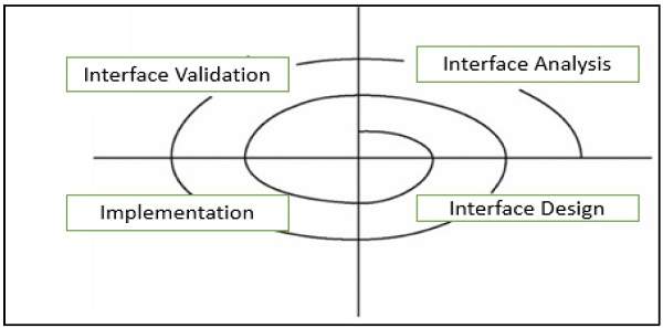
Interface analysis
It concentrates or focuses on users, tasks, content, and work environment who will interact with the system. Defines the human - and computer-oriented tasks that are required to achieve system function.
Interface design
It defines a set of interface objects, actions, and their screen representations that enable a user to perform all defined tasks in a manner that meets every usability objective defined for the system.
Interface construction
It starts with a prototype that enables usage scenarios to be evaluated and continues with development tools to complete the construction.
Interface validation
It focuses on the ability of the interface to implement every user task correctly, accommodate all task variations, to achieve all general user requirements, and the degree to which the interface is easy to use and easy to learn.
When a user interface is analyzed and designed following four models are used −
User profile model
Created by a user or software engineer, which establishes the profile of the end-users of the system based on age, gender, physical abilities, education, motivation, goals, and personality.
Considers syntactic and semantic knowledge of the user and classifies users as novices, knowledgeable intermittent, and knowledgeable frequent users.
Design model
Created by a software engineer which incorporates data, architectural, interface, and procedural representations of the software.
Derived from the analysis model of the requirements and controlled by the information in the requirements specification which helps in defining the user of the system.
Implementation model
Created by the software implementers who work on look and feel of the interface combined with all supporting information (books, videos, help files) that describes system syntax and semantics.
Serves as a translation of the design model and attempts to agree with the user's mental model so that users then feel comfortable with the software and use it effectively.
User's mental model
Created by the user when interacting with the application. It contains the image of the system that users carry in their heads.
Often called the user's system perception and correctness of the description depends upon the user’s profile and overall familiarity with the software in the application domain.
A user interface must be a user-centered product which involves users throughout a product’s development lifecycle. The prototype of a user interface should be available to users and feedback from users, should be incorporated into the final product.
UI provides simplicity and intuitiveness so that it can be used quickly and effectively without instructions. GUI are better than textual UI, as GUI consists of menus, windows, and buttons and is operated by simply using mouse.
Do not force users to complete predefined sequences. Give them options—to cancel or to save and return to where they left off. Use terms throughout the interface that users can understand, rather than system or developer terms.
Provide users with some indication that an action has been performed, either by showing them the results of the action, or acknowledging that the action has taken place successfully.
UI must be transparent that helps users to feel like they are reaching right through computer and directly manipulating the objects they are working with. The interface can be made transparent by giving users work objects rather than system objects. For example, users should understand that their system password must be at least 6 characters, not how many bytes of storage a password must be.
Always provide easy access to common features and frequently used actions. Hide less common features and actions and allow users to navigate them. Do not try to put every piece of information in one main window. Use secondary window for information that is not key information.
UI maintains the consistency within and across product, keep interaction results the same, UI commands and menus should have the same format, command punctuations should be similar and parameters should be passed to all commands in the same way. UI should not have behavior’s that can surprise the users and should include the mechanisms that allows users to recover from their mistakes.
The software system should integrate smoothly with other applications such as MS notepad and MS-Office. It can use Clipboard commands directly to perform data interchange.
UI design must be modular and incorporate component oriented architecture so that the design of UI will have the same requirements as the design of the main body of the software system. The modules can easily be modified and replaced without affecting of other parts of the system.
The architecture of whole software system incorporates plug-in modules, which allow many different people independently extend the software. It allows individual users to select from various available forms in order to suit personal preferences and needs.
Do not force users to have to remember and repeat what the computer should be doing for them. For example, when filling in online forms, customer names, addresses, and telephone numbers should be remembered by the system once a user has entered them, or once a customer record has been opened.
User interfaces support long-term memory retrieval by providing users with items for them to recognize rather than having to recall information.
UI must be separated from the logic of the system through its implementation for increasing reusability and maintainability.
It is an iterative and incremental approach consisting of five main steps that helps to generate candidate solutions. This candidate solution can further be refined by repeating these steps and finally create an architecture design that best fits our application. At the end of the process, we can review and communicate our architecture to all interested parties.
It is just one possible approach. There are many other more formal approaches that defining, reviewing, and communicating your architecture.
Identify the architecture goal that forms the architecture and design process. Flawless and defined objectives emphasize on the architecture, solve the right problems in the design and helps to determine when the current phase has completed, and ready to move to the next phase.
This step includes the following activities −
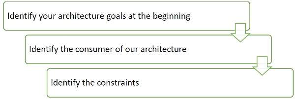
Examples of architecture activities include building a prototype to get feedback on the order-processing UI for a Web application, building a customer order-tracking application, and designing the authentication, and authorization architecture for an application in order to perform a security review.
This step puts emphasis on the design that matters the most. A scenario is an extensive and covering description of a user's interaction with the system.
Key scenarios are those that are considered the most important scenarios for the success of your application. It helps to make decisions about the architecture. The goal is to achieve a balance among the user, business, and system objectives. For example, user authentication is a key scenario because they are an intersection of a quality attribute (security) with important functionality (how a user logs into your system).
Build an overview of application, which makes the architecture more touchable, connecting it to real-world constraints and decisions. It consists of the following activities −
Identify Application Type
Identify application type whether it is a mobile application, a rich client, a rich internet application, a service, a web application, or some combination of these types.
Identify Deployment Constraints
Choose an appropriate deployment topology and resolve conflicts between the application and the target infrastructure.
Identify Important Architecture Design Styles
Identify important architecture design styles such as client/server, layered, message-bus, domain-driven design, etc. to improve partitioning and promotes design reuse by providing solutions to frequently recurring problems. Applications will often use a combination of styles.
Identify the Relevant Technologies
Identify the relevant technologies by considering the type of application we are developing, our preferred options for application deployment topology and architectural styles. The choice of technologies will also be directed by organization policies, infrastructure limitations, resource skills, and so on.
While designing an application, hot spots are the zones where mistakes are most often made. Identify key issues based on quality attributes and crosscutting concerns. Potential issues include the appearance of new technologies and critical business requirements.
Quality attributes are the overall features of your architecture that affect run-time behavior, system design, and user experience. Crosscutting concerns are the features of our design that may apply across all layers, components, and tiers.
These are also the areas in which high-impact design mistakes are most often made. Examples of crosscutting concerns are authentication and authorization, communication, configuration management, exception management and validation, etc.
After defining the key hotspots, build the initial baseline architecture or first high level design and then start to fill in the details to generate candidate architecture.
Candidate architecture includes the application type, the deployment architecture, the architectural style, technology choices, quality attributes, and crosscutting concerns. If the candidate architecture is an improvement, it can become the baseline from which new candidate architectures can be created and tested.
Validate the candidate solution design against the key scenarios and requirements that have already defined, before iteratively following the cycle and improving the design.
We may use architectural spikes to discover the specific areas of the design or to validate new concepts. Architectural spikes are a design prototype, which determine the feasibility of a specific design path, reduce the risk, and quickly determine the viability of different approaches. Test architectural spikes against key scenarios and hotspots.
Architecture review is the most important task in order to reduce the cost of mistakes and to find and fix architectural problems as early as possible. It is a well-established, cost-effective way of reducing project costs and the chances of project failure.
Review the architecture frequently at major project milestones, and in response to other significant architectural changes.
The main objective of an architecture review is to determine the feasibility of baseline and candidate architectures, which verify the architecture correctly.
Links the functional requirements and the quality attributes with the proposed technical solution. It also helps to identify issues and recognize areas for improvement
Scenario-based evaluations are a dominant method for reviewing an architecture design which focuses on the scenarios that are most important from the business perspective, and which have the greatest impact on the architecture.
Following are common review methodologies −
Software Architecture Analysis Method (SAAM) − It is originally designed for assessing modifiability, but later was extended for reviewing architecture with respect to quality attributes.
Architecture Tradeoff Analysis Method (ATAM) − It is a polished and improved version of SAAM, which reviews architectural decisions with respect to the quality attributes requirements, and how well they satisfy particular quality goals.
Active Design Review (ADR) − It is best suited for incomplete or in-progress architectures, which more focus on a set of issues or individual sections of the architecture at a time, rather than performing a general review.
Active Reviews of Intermediate Designs (ARID) − It combines the ADR aspect of reviewing in-progress architecture with a focus on a set of issues, and the ATAM and SAAM approach of scenario-based review focused on quality attributes.
Cost Benefit Analysis Method (CBAM) − It focuses on analyzing the costs, benefits, and schedule implications of architectural decisions.
Architecture Level Modifiability Analysis (ALMA) − It estimates the modifiability of architecture for business information systems (BIS).
Family Architecture Assessment Method (FAAM) − It estimates information system family architectures for interoperability and extensibility.
After completing the architecture design, we must communicate the design to the other stakeholders, which include development team, system administrators, operators, business owners, and other interested parties.
There are several following well-known methods for describing architecture to others: −
This approach uses five views of the complete architecture. Among them, four views (the logical view, the process view, the physical view, and the development view) describe the architecture from different approaches. A fifth view shows the scenarios and use cases for the software. It allows stakeholders to see the features of the architecture that specifically interest them.
This approach is used to describe software architecture prior to the system implementation. It addresses the following concerns − behavior, protocol, and connector.
The main advantage of ADL is that we can analyze the architecture for completeness, consistency, ambiguity, and performance before formally beginning use of the design.
This approach follows the concept that “content is more important than representation.” It ensures that the models created are simple and easy to understand, sufficiently accurate, detailed, and consistent.
Agile model documents target specific customer(s) and fulfill the work efforts of that customer. The simplicity of the document ensures that there is active participation of stakeholders in the modeling of the artifact.
IEEE 1471 is the short name for a standard formally known as ANSI/IEEE 1471-2000, “Recommended Practice for Architecture Description of Software-Intensive Systems.” IEEE 1471 enhances the content of an architectural description, in particular, giving specific meaning to context, views, and viewpoints.
This approach represents three views of a system model. The functional requirements view (functional requirements of the system from the point of view of the user, including use cases); the static structural view (objects, attributes, relationships, and operations including class diagrams); and the dynamic behavior view (collaboration among objects and changes to the internal state of objects, including sequence, activity, and state diagrams).