facade.bmp (32014 bytes) A façade is a packaged subset of work products selected from the contents of a subsystem.  Each façade provides public access to only those parts of the subsystem that have been chosen to be available for reuse.  The façades are presented as stereotyped UML packages using the stereotype <<façade>>.

In other words, a model element that defines a subsystem interface.

Related Information:

Topics

Introduction To top of page

A façade acts as a public interface to a subsystem.  A façade provides a simplified interface to a complicated model.

A façade is a re-user's view of a subsystem.  It simplifies the job for re-users who wish to use the subsystem (and therefore the components) presented by the façade.   The façade, and its contents, should be selected and documented so that re-users need to only understand the façade and not any of the other details of the component.

Façades are used when:

  • You want a simpler interface to a complex subsystem.
  • There are many dependencies between clients and the implementation classes of an abstraction.  Facades are introduced to de-couple the subsystem from clients and other subsystems, thereby promoting subsystem independence and portability.
  • You want to layer your subsystems.  Use a façade to define an entry point to each subsystem level.  If subsystems are dependent, then you can simplify the dependencies between them by making them communicate with each other solely through their facades.

Making use of the façade pattern offers the following benefits:

  • It shields clients from the implementation details of subsystems/components, thereby reducing the number of objects that clients deal with and making the subsystem easier to use
  • It promotes weak coupling between the subsystem and its clients. Often the components in a subsystem are strongly coupled. Weak coupling lets you vary the components of the subsystem without affecting the clients.
  • Facades help layer a system and the dependencies between objects. They can eliminate complex or circular dependencies. This can be an important consequence when the client and the subsystems are implemented independently
  • The use of facades lends itself to the modeling of stateless services and subsystems.
  • When modeling the subsystem clients only the Façade needs to be loaded into the client model.

Another benefit of adopting the façade approach is that the facades provide a valuable focus for client/server interactions when the implementation is based on the server. A useful technique in these cases is to "stretch" the façade across the client and the server, placing a façade class on both the client and the server. The client side facades would now operate as a proxy, as well as an interface definition, and can then have built in intelligence to handle issues such as marshalling and data type conversions.

Naming Standard To top of page

The general package naming standards apply to <<facade>> packages (See Standards: Package Overview).

Diagramming Standards To top of page

Diagram Purpose Use Comment
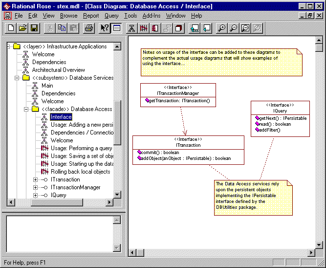
Main / Interface *1 A class diagram showing the full interface presented by the facade. Mandatory A diagram showing the full interface of the subsystem as presented by the facade.  This must include all classes that are part of the interface (including those passed as parameters to methods that are part of the interface).

Note: You should never attempt to combine this diagram with any other diagrams.

Usage A set of interaction (sequence) and / or class diagrams showing how the clients of the subsystem should use the facade.

Naming convention:

Usage: diagram name

Mandatory These diagrams show how a client would use the subsystem. It should not describe any internal behavior.

Typical examples include:
· Initialize subsystem
· Shutdown subsystem
· Complex patterns of usage

The sequence diagram should state [Preconditions] and [postconditions] at the start and end of the trace.

Dependencies A class diagram showing which other packages the subsystem facade is dependent on. Mandatory* *Not required if the facade is not dependent on any other packages.

This would include dependencies to all of the packages from which the individual interfaces are imported or which supply model elements that the subsystems interface is dependent upon.

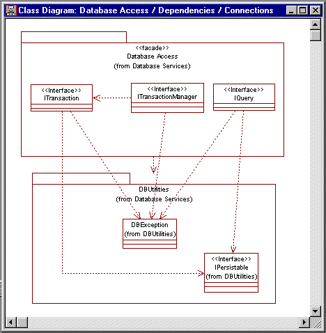
Connections  A class diagram showing which other interfaces and classes the components of the facade are dependent on. Mandatory* *Not required if the facade is not dependent on any other packages.

This would include dependencies to all of the interface and utility classes upon which the facade is dependent.

This is the only internal design documentation required for a facade.

This diagram can often be combined with the Dependencies diagram to show both the package level dependencies and the class level connections (i.e. Diagram named Dependencies / Connections)

Welcome A class diagram presenting the purpose of the facade. Optional An explanatory diagram welcoming users to the facade.

Notes:

*1 - The Main/Interface diagram is sometimes referred to as the Interface Realizations diagram (See the RUP: Rose Tool Mentors).

Constraints To top of page

Constraints: <<facade>> packages can contain only interfaces (i.e. interface classes).  All classes in the facade are considered public.

Notes: <<implementation>> packages will implement the interfaces defined by the <<facade>> packages (See RUP Guidelines: Design Subsystem and Standards: Implementation Packages).

Examples To top of page

An example  <<facade>> package is shown below, with its Interface diagram displayed.  The browser   shows the presence of a set of Usage diagrams explaining how the services offered by the facade's interface should be used.
wpeB.gif (30174 bytes)

The Dependencies / Connections diagram shows how the facade depends upon the underlying Data Base Utilities package:
wpeC.gif (11308 bytes)

Back to Index
 

Display Organization Process Web using frames

Copyright  © 1987 - 2001 Rational Software Corporation 

Wylie College Process Web Example
Version 2001.02